Getting Started with Bluetooth LE on the Arduino Nano 33 Sense

This article will show you how to program the Arduino Nano BLE 33 devices to use Bluetooth LE.

Introduction

Bluetooth Low Energy and I go way back. I was one of the first using the HM-10 module back in the day. Recently, my mentor introduced me to the Arduino Nano 33 BLE Sense. Great little board–packed with sensors!

Shortly after firing it up, I got excited. I’ve been wanting to start creating my own smartwatch for a long time (as long the Apple watch has sucked really). And it looks like I wasn’t the only one:

This one board had many of the sensors I wanted, all in one little package. The board is a researcher’s nocturnal emission.

Of course, my excitement was tamed when I realized there weren’t tutorials on how to use the Bluetooth LE portion. So, after a bit of hacking I figured I’d share what I’ve learned.

Blue on Everything

This article will be part of a series. Here, we will be building a Bluetooth LE peripheral from the Nano 33, but it’s hard to debug without having a central device to find and connect to the peripheral.

The next article in this series will show how to use use Python to connect to Bluetooth LE peripherals (above gif). This should allow one to connect to the Nano 33 from a PC. In short, stick with me. I’ve more Bluetooth LE content coming.

How to Install the Arduino Nano 33 BLE Board

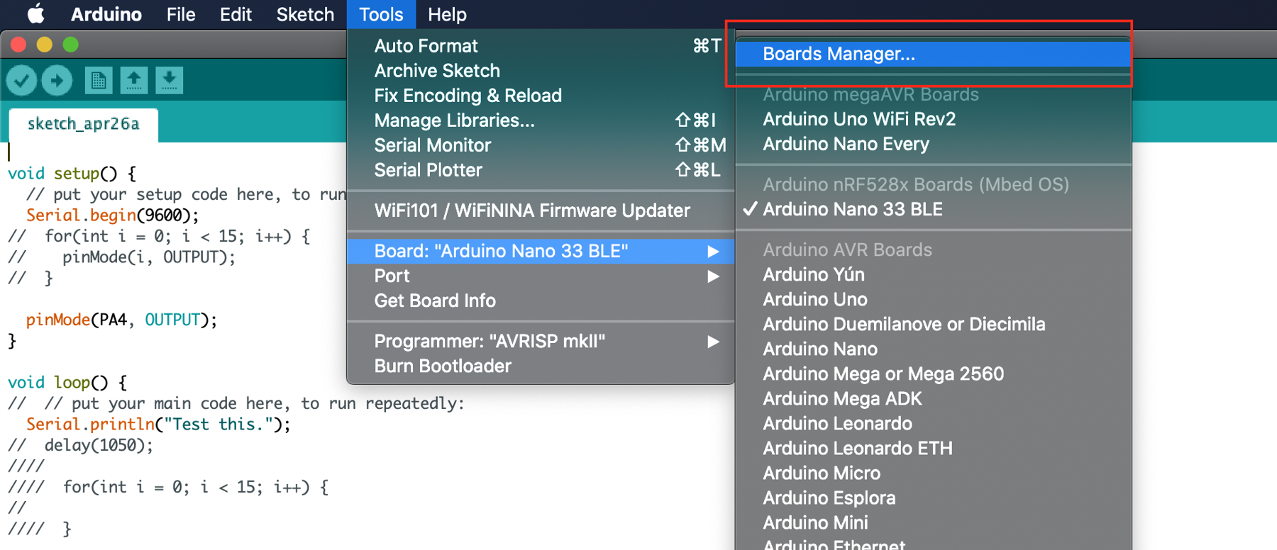
After getting your Arduino Nano 33 BLE board there’s a little setup to do. First, open up the Arduino IDE and navigate to the “Boards Manager.”

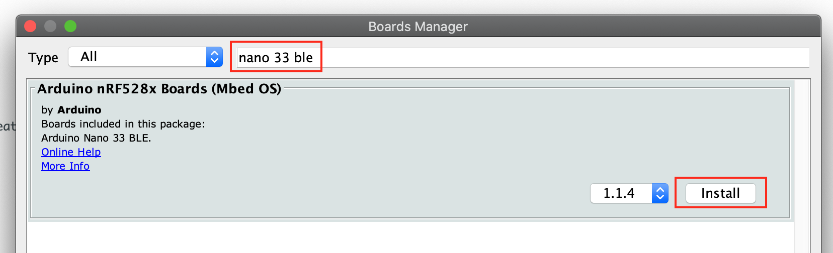
Search for Nano 33 BLE and install the board Arduino nRF528xBoards (MBed OS).

Your Arduino should be ready work with the Nano 33 boards, except BLE. For that, we need another library.

How to Install the ArduinoBLE Library

There are are a few different Arduino libraries for Bluetooth LE–usually, respective to the hardware. Unfortunate, as this means we would need a different library to work with the Bluetooth LE on a ESP32, for example. Oh well. Back to the problem at hand.

The official library for working with the Arduino boards equipped with BLE is:

It works pretty well, though, the documentation is a bit spotty.

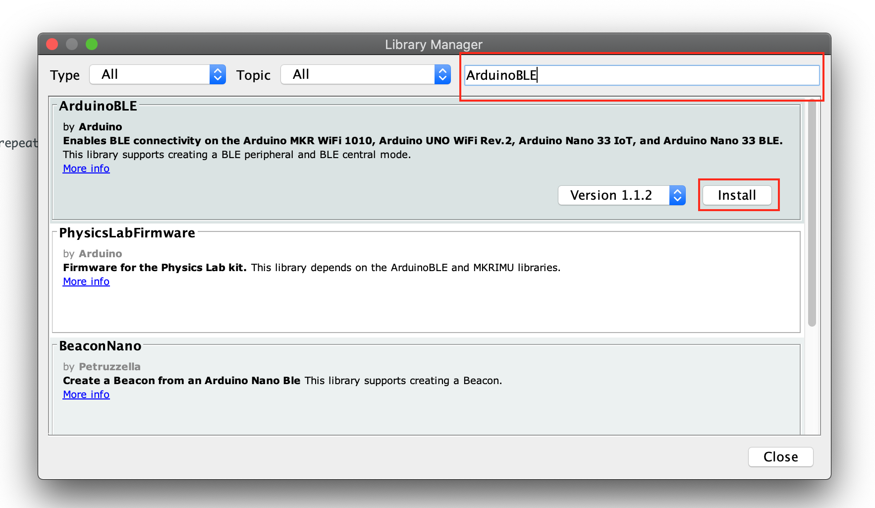
To get started you’ll need to fire up the Arduino IDE and go to Tools then Manager Libraries...

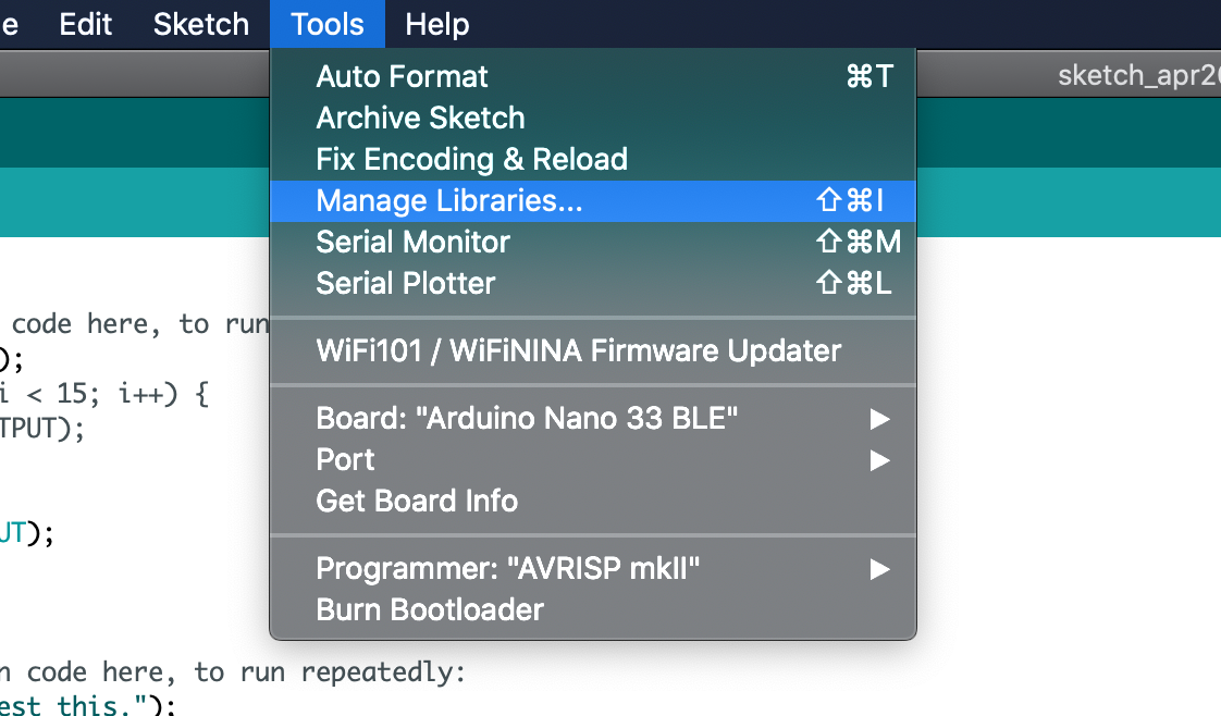
In the search box that comes up type ArduinoBLE and then select Install next to the library:

That’s pretty much it, we can now include the library at the top of our sketch:

#include <ArduinoBLE.h>

And access the full API in our code.

Project Description

If you are eager, feel free to skip this information and jump to the code.

Before moving on, if the following terms are confusing:

  • Peripheral
  • Central
  • Master
  • Slave
  • Server
  • Client

You might check out EmbeddedFM’s explanation:

I’ll be focusing on getting the Arduino 33 BLE Sense to act as a peripheral BLE device. As a peripheral, it’ll advertise itself as having services, one for reading, the other for writing.

UART versus Bluetooth LE

Usually when I’m working with a Bluetooth LE (BLE) device I want it to send and receive data. And that’ll be the focus of this article.

I’ve seen this send-n-receive’ing data from BLE referred to as “UART emulation.” I think that’s fair, UART is a classic communication protocol for a reason. I’ve like the comparison as a mental framework for our BLE code.

We will have a rx property to get data from a remote device and a tx property where we can send data. Throughout the Arduino program you’ll see my naming scheme using this analog. That stated, there are clear differences between BLE communication and UART. BLE is arguably more complex and versatile.

Data from the Arduino Microphone

To demonstrate sending and receiving data we need to data to send. We are going to grab information from the microphone on the Arduino Sense and send it to remote connected device. I’ll not cover the microphone code here, as I don’t understand it well enough to explain. However, here’s a couple reads:

Code

Time to code. Below is what I hacked together, with annotations from the “gotchas” I ran into.

One last caveat, I used Jithin’s code as a base of my project:

Although, I’m not sure any of the original code is left. Cite your sources.

And if you’d rather look at the full code, it can be found at:

Initialization

We load in the BLE and the PDM libraries to access the APIs to work with the microphone and the radio hardware.


#include <ArduinoBLE.h>
#include <PDM.h>

Service and Characteristics

Let’s create the service. First, we create the name displayed in the advertizing packet, making it easy for a user to identify our Arduino.

We also create a Service called microphoneService, passing it the full Universally Unique ID (UUID) as a string. When setting the UUID there are two options. A 16-bit or a 128-bit version. If you use one of the standard Bluetooth LE Services the 16-bit version is good. However, if you are looking to create a custom service, you will need to explore creating a full 128-bit UUID.

Here, I’m using the full UUIDs but with a standard service and characteristic, as it makes it easier to connect other hardware to our prototype, as the full UUID is known.

If you want to understand UUID’s more fully, I highly recommend Nordic’s article:

Anyway, we are going to use the following UUIDs:

You may notice reading the Bluetooth specifications, there are two mandatory characteristics we should be implementing for Generic Access:

For simplicity, I’ll leave these up to the reader. But they must be implemented for a proper Generic Access service.

Right, back to the code.

Here we define the name of the device as it should show to remote devices. Then, the service and two characteristics, one for sending, the other, receiving.

// Device name
const char* nameOfPeripheral = "Microphone";
const char* uuidOfService = "0000181a-0000-1000-8000-00805f9b34fb";
const char* uuidOfRxChar = "00002A3D-0000-1000-8000-00805f9b34fb";
const char* uuidOfTxChar = "00002A58-0000-1000-8000-00805f9b34fb";

Now, we actually instantiate the BLEService object called microphoneService.

// BLE Service
BLEService microphoneService(uuidOfService);

The characteristic responsible for receiving data, rxCharacteristic, has a couple of parameters which tell the Nano 33 how the characteristic should act.

// Setup the incoming data characteristic (RX).
const int RX_BUFFER_SIZE = 256;
bool RX_BUFFER_FIXED_LENGTH = false;

RX_BUFFER_SIZE will be how much space is reserved for the rx buffer. And RX_BUFFER_FIXED_LENGTH will be, well, honestly, I’m not sure. Let me take a second and try to explain my ignorance.

When looking for the correct way to use the ArduinoBLE library, I referred to the documentation:

There are several different ways to initialize a characteristic, as a single value (e.g., BLEByteCharacteristic, BLEFloatCharacteristic, etc.) or as buffer. I decided on the buffer for the rxCharacteristic. And that’s where it got problematic.

Here’s what the documentation states regarding initializing a BLECharacteristic with a buffer.

BLECharacteristic(uuid, properties, value, valueSize)
BLECharacteristic(uuid, properties, stringValue)
...
uuid: 16-bit or 128-bit UUID in string format
properties: mask of the properties (BLEBroadcast, BLERead, etc)
valueSize: (maximum) size of characteristic value
stringValue: value as a string

Cool, makes sense. Unfortunately, I never got a BLECharacteristic to work initializing it with those arguments. I finally dug into the actual BLECharacteristic source and discovered their are two ways to initialize a BLECharacteristic:

BLECharacteristic(new BLELocalCharacteristic(uuid, properties, valueSize, fixedLength))
BLECharacteristic(new BLELocalCharacteristic(uuid, properties, value))

I hate misinformation. Ok, that tale aside, back to our code.

Let’s actually declare the rx and tx characteristics. Notice, we are using a buffered characteristic for our rx and a single byte value characteristic for our tx. This may not be optimal, but it’s what worked.

// RX / TX Characteristics
BLECharacteristic rxChar(uuidOfRxChar, BLEWriteWithoutResponse | BLEWrite, RX_BUFFER_SIZE, RX_BUFFER_FIXED_LENGTH);
BLEByteCharacteristic txChar(uuidOfTxChar, BLERead | BLENotify | BLEBroadcast);

The second argument is where you define how the characteristic should behave. Each property should be separated by the | as they are constants which are being ORed together into a single value (masking).

Here is a list of available properties:

  • BLEBroadcast – will cause the characteristic to be advertized
  • BLERead – allows remote devices to read the characteristic value
  • BLEWriteWithoutResponse – allows remote devices to write to the device without expecting an acknowledgement
  • BLEWrite – allows remote devices to write, while expecting an acknowledgement the write was successful
  • BLENotify – allows a remote device to be notified anytime the characteristic’s value is update
  • BLEIndicate – the same as BLENotify, but we expect a response from the remote device indicating it read the value

Microphone

There are two global variables which keep track of the microphone data. The first is a small buffer called sampleBuffer, it will hold up to 256 values from the mic.

The volatile int samplesRead is the variable which will hold the immediate value from the mic sensor. It is used in the interrupt routine vector (ISR) function. The volatile keyword tells the Arduino’s C++ compiler the value in the variable may change at any time and it should check the value when referenced, rather than relying on a cached value in the processor (more on volatiles).

// Buffer to read samples into, each sample is 16-bits
short sampleBuffer[256];

// Number of samples read
volatile int samplesRead;

Setup()

We initialize the Serial port, used for debugging.

void setup() {

  // Start serial.
  Serial.begin(9600);

  // Ensure serial port is ready.
  while (!Serial);

To see when the BLE actually is connected, we set the pins connected to the built-in RGB LEDs as OUTPUT.

  // Prepare LED pins.
  pinMode(LED_BUILTIN, OUTPUT);
  pinMode(LEDR, OUTPUT);
  pinMode(LEDG, OUTPUT);

Note, there is a bug in the source code where the LEDR and the LEDG are backwards. You can fix this by searching your computer for ARDUINO_NANO33BLE folder and editing the file pins_arduino.h inside.

Change the following:

#define LEDR        (22u)
#define LEDG        (23u)
#define LEDB        (24u)

To

#define LEDR        (23u)
#define LEDG        (22u)
#define LEDB        (24u)

And save. That should fix the mappings.

The onPDMdata() is an ISR which fires every time the microphone gets new data. And startPDM() starts the microphone integrated circuit.

  // Configure the data receive callback
  PDM.onReceive(onPDMdata);

  // Start PDM
  startPDM();

Now Bluetooth LE is setup, we ensure the Bluetooth LE hardware has been powered-on within the Nano 33. We set the device name and begin advertizing the service. Then, add the rx and tx characteristics to the microphoneService. Lastly, add the microphoneService to the BLE object.

  // Start BLE.
  startBLE();

  // Create BLE service and characteristics.
  BLE.setLocalName(nameOfPeripheral);
  BLE.setAdvertisedService(microphoneService);
  microphoneService.addCharacteristic(rxChar);
  microphoneService.addCharacteristic(txChar);
  BLE.addService(microphoneService);

Now the Bluetooth LE hardware is turned on, we add callbacks which will fire when the device connects or disconnects. Those callbacks are great places to add notifications, setup, and teardown.

We also add a callback which will fire every time the Bluetooth LE hardware has a characteristic written. This allows us to handle data as it streams in.

  // Bluetooth LE connection handlers.
  BLE.setEventHandler(BLEConnected, onBLEConnected);
  BLE.setEventHandler(BLEDisconnected, onBLEDisconnected);

  // Event driven reads.
  rxChar.setEventHandler(BLEWritten, onRxCharValueUpdate);

Lastly, we command the Bluetooth LE hardware to begin advertizing its services and characteristics to the world. Well, at least +/-30ft of the world.

  // Let's tell devices about us.
  BLE.advertise();

Before beginning the main loop, I like spiting out all of the hardware information we setup. This makes it easy to add it into whatever other applications we are developing., which will connect to the newly initialized peripheral.

  // Print out full UUID and MAC address.
  Serial.println("Peripheral advertising info: ");
  Serial.print("Name: ");
  Serial.println(nameOfPeripheral);
  Serial.print("MAC: ");
  Serial.println(BLE.address());
  Serial.print("Service UUID: ");
  Serial.println(microphoneService.uuid());
  Serial.print("rxCharacteristic UUID: ");
  Serial.println(uuidOfRxChar);
  Serial.print("txCharacteristics UUID: ");
  Serial.println(uuidOfTxChar);
  

  Serial.println("Bluetooth device active, waiting for connections...");
}

Loop()

The main loop grabs a reference to the central property from the BLE object. It checks if central exists and then it checks if central is connected. If it is, it calls the connectedLight() which will cause the green LED to come on, letting us know the hardware has made a connection.

Then, it checks if there are data in the sampleBuffer array, if so, it writes them to the txChar. After it has written all data, it resets the samplesRead variable to 0.

Lastly, if the device is not connected or not initialized, the loop turns on the disconnected light by calling disconnectedLight().

void loop()
{
  BLEDevice central = BLE.central();
  
  if (central)
  {
    // Only send data if we are connected to a central device.
    while (central.connected()) {
      connectedLight();

      // Send the microphone values to the central device.
      if (samplesRead) {
        // print samples to the serial monitor or plotter
        for (int i = 0; i < samplesRead; i++) {
          txChar.writeValue(sampleBuffer[i]);      
        }
        // Clear the read count
        samplesRead = 0;
      }
    }
    disconnectedLight();
  } else {
    disconnectedLight();
  }
}

Some may have noticed there is probably an issue with how I’m pulling the data from the sampleBuffer, as I’ve just noticed it myself writing this article, it may have a condition where the microphone’s ISR is called in the middle of writing the buffer to the txChar. If I’ve need to fix this, I’ll update this article.

Ok, hard part’s over, let’s move on to the helper methods.

Helper Methods

startBLE()

The startBLE() function initializes the Bluetooth LE hardware by calling the begin(). If it is unable to start the hardware, it will state so via the serial port, and then stick forever.

/*
 *  BLUETOOTH
 */
void startBLE() {
  if (!BLE.begin())
  {
    Serial.println("starting BLE failed!");
    while (1);
  }
}

onRxCharValueUpdate()

This method is called when new data is received from a connected device. It grabs the data from the rxChar by calling readValue and providing a buffer for the data and how many bytes are available in the buffer. The readValue method returns how many bytes were read. We then loop over each of the bytes in our tmp buffer, cast them to char, and print them to the serial terminal. This is pretty helpful when debugging.

Before ending, we also print out how many bytes were read, just in case we’ve received data which can’t be converted to ASCII. Again, helpful for debugging.

void onRxCharValueUpdate(BLEDevice central, BLECharacteristic characteristic) {
  // central wrote new value to characteristic, update LED
  Serial.print("Characteristic event, read: ");
  byte tmp[256];
  int dataLength = rxChar.readValue(tmp, 256);

  for(int i = 0; i < dataLength; i++) {
    Serial.print((char)tmp[i]);
  }
  Serial.println();
  Serial.print("Value length = ");
  Serial.println(rxChar.valueLength());
}

LED Indicators

Not much to see here. These functions are called when our device connects or disconnects, respectively.

void onBLEConnected(BLEDevice central) {
  Serial.print("Connected event, central: ");
  Serial.println(central.address());
  connectedLight();
}

void onBLEDisconnected(BLEDevice central) {
  Serial.print("Disconnected event, central: ");
  Serial.println(central.address());
  disconnectedLight();
}

/*
 * LEDS
 */
void connectedLight() {
  digitalWrite(LEDR, LOW);
  digitalWrite(LEDG, HIGH);
}


void disconnectedLight() {
  digitalWrite(LEDR, HIGH);
  digitalWrite(LEDG, LOW);
}

Microphone

I stole this code from Arduino provided example. I think it initializes the PDM hardware (microphone) with a 16khz sample rate.

/*
 *  MICROPHONE
 */
void startPDM() {
  // initialize PDM with:
  // - one channel (mono mode)
  // - a 16 kHz sample rate
  if (!PDM.begin(1, 16000)) {
    Serial.println("Failed to start PDM!");
    while (1);
  }
}

Lastly, the onPDMData callback is fired whenever their are data available to be read. It checks how many bytes their are available by calling available() and reads that number of bytes into the buffer. Lastly, given the data are int16, it divides the number of bytes by 2 as this is the number of samples read.

void onPDMdata() {
  // query the number of bytes available
  int bytesAvailable = PDM.available();

  // read into the sample buffer
  int bytesRead = PDM.read(sampleBuffer, bytesAvailable);

  // 16-bit, 2 bytes per sample
  samplesRead = bytesRead / 2;
}

Final Thoughts

Bluetooth LE is powerful–but tough to get right. To be clear, not saying I’ve gotten it right here, but I’m hoping I’m closer. If you find any issues please leave me a comment or send me an email and I’ll get them corrected as quick as I’m able.

Arduino RAMPs 1.4 Custom Firmware

This article is part of a series documenting an attempt to create a LEGO sorting machine. This portion covers the Arduino Mega2560 firmware I’ve written to control a RAMPS 1.4 stepper motor board.

A big thanks to William Cooke, his wisdom was key to this project. Thank you, sir!

Goal

To move forward with the LEGO sorting machine I needed a way to drive a conveyor belt. Stepper motors were a fairly obvious choice. They provide plenty of torque and finite control. This was great, as several other parts of the LEGO classifier system would need steppers motors as well-e.g.,turn table and dispensing hopper. Of course, one of the overall goals of this project is to keep the tools accessible. After some research I decided to meet both goals by purchasing an Ardunio / RAMPs combo package intended for 3D printers.

At the time of the build, these kits were around $28-35 and included:

  • Arduino Mega2560
  • 4 x Endstops
  • 5 x Stepers Drivers (A4988)
  • RAMPSs 1.4 board
  • Display
  • Cables & wires

Seemed like a good deal. I bought a couple of them.

I would eventually need:

  • 3 x NEMA17 stepper motors
  • 12v, 10A Power Supply Unit (PSU)

Luckily, I had the PSU and a few stepper motors lying about the house.

Physical Adjustments

Wiring everything up wasn’t too bad. You follow about any RAMPs wiring diagram. However, I did need to make two adjustments before starting on the firmware.

First, underneath each of the stepper drivers there are three drivers for setting the microsteps of the respective driver. Having all three jumpers enables maximum microsteps, but would cause the speed of the motor to be limited by the clock cycles of the Arduino–more on that soon.

I’ve also increased the amperage to the stepper. This allowed me to drive the entire belt from one NEMA17.

To set the amperage, get a small phillips screwdriver, two alligator clips, and a multimeter. Power on your RAMPs board and carefully attach the negative probe to the RAMPs GND. Attach the positive probe to an alligator clip and attach the other end to the shaft of your screwdriver. Use the screwdriver to turn the tiny potentiometer on the stepper driver. Watch the voltage on the multimeter–we want to use the lowest amperage which effectively drives the conveyor belt. We are watching the voltage, as it is related to the amperage we are feeding the motors.

current_limit = Vref x 2.5

Anyway, I found the lowest point for my motor, without skipping steps, was around ~0.801v.

current_limit = 0.801 x 2.5
current_limit = 2.0025

The your current_limit will vary depending on the drag of your conveyor belt and the quality of your stepper motor. To ensure a long-life of your motor, do not set the amperage higher than needed to do the job.

Arduino Code

When I bought the RAMPs board I started thinking, “I should see if we could re-purpose Marlin to drive the conveyor belt easily.” I took one look at the source and said, “Oh hell no.” Learning how to hack Marlin to drive a conveyor belt seemed like learning heart surgery to hack your heart into a gas pump. So, I decided roll my own RAMPs firmware.

My design goals were simple:

  • Motors operate independently
  • Controlled with small packets via UART
  • Include four commands: motor select, direction, speed, duration

That’s it. I prefer to keep stuff as simple as possible, unless absolutely necessary.

I should point out, this project builds on a previous attempt at firmware:

But that code was flawed. It was not written with concurrent and independent motor operation in mind. The result, only one motor could be controlled at a time.

Ok, on to the new code.

Main

The firmware follows this procedure:

  1. Check if a new movement packet has been received.
  2. Decode the packet
  3. Load direction, steps, and delay (speed) into the appropriate motor struct.
  4. Check if a motor has steps to take and the timing window for the next step is open.
  5. If a motor has steps waiting to be taken, move the motor one step and decrement the respective motor’s step counter.
  6. Repeat forever.
/* Main */
void loop()
{
  if (rxBuffer.packet_complete) {
    // If packet is packet_complete
    handleCompletePacket(rxBuffer);
    // Clear the buffer for the next packet.
    resetBuffer(&rxBuffer);
  }
  
  // Start the motor
  pollMotor();
}

serialEvent

Some code not in the main loop is the the UART RX handler. It is activated by an RX interrupt. If the interrupt fires, the new data is quickly loaded into the rxBuffer. If the incoming data contains a 0x03 character, this signals the packet is complete and ready to be decoded.

Here’s the packet template:

MOTOR_PACKET = CMD_TYPE MOTOR_NUM DIR STEPS_1 STEPS_2 MILLI_BETWEEN 0x03

Each motor movement packet consists of seven bytes and five values:

  1. CMD_TYPE = drive or halt
  2. MOTOR_NUM = the motor selected X, Y, Z, E0, E1
  3. DIR = direction of the motor
  4. STEPS_1 = the high 6-bits of of steps to take
  5. STEPS_2 = the low 6-bits of steps to take
  6. MILLI_BETWEEN = number of milliseconds between each step (speed control)
  7. 0x03 = this signals the end of the packet (ETX)

Each of these bytes are encoded by left-shifting the bits by two. This means each of the bytes in the packet can only represent 64 values (2^6 = 64).

Why add this complication? Well, we want to be able to send commands to control the firmware, rather than the motors. The most critical is knowing when the end of a packet is reached. I’m using the ETX char, 0x03 to signal the end of a packet. If we didn’t reserve the 0x03 byte then what happens if we send command to the firmware to move the motor 3 steps? Nothing good.

Here’s the flow of a processed command:

1. CMD_TYPE       = DRIVE (0x01)
2. MOTOR_NUM      = X     (0x01)
3. DIR            = CW    (0x01)
4. STEPS          = 4095  (0x0FFF)
5. MILLI_BETWEEN  = 5ms   (0x05)
6. ETX            = End   (0x03)

Note, the maximum value of the STEPS byte is greater than 8-bits. To handle this, we break it into two bytes of 6-bits.

1. CMD_TYPE       = DRIVE (0x01)
2. MOTOR_NUM      = X     (0x01)
3. DIR            = CW    (0x01)
4. STEPS_1        = 3F
5. STEPS_2        = 3F
5. MILLI_BETWEEN  = 5     (0x05)
6. ETX            = End   (0x03)

Here’s a sample motor packet before encoding:

uint8_t packet[7] = {0x01, 0x01, 0x01, 0x3F, 0x3F, 0x05, 0x03}

Now, we have to shift all of the bytes left by two bits, this will ensure 0x00 through 0x03 are reserved for meta-communication.

This process is a bit easier to see in binary:

Before shift:

1. CMD_TYPE       = 0000 0001
2. MOTOR_NUM      = 0000 0001
3. DIR            = 0000 0001
4. STEPS_1        = 0011 1111
5. STEPS_2        = 0011 1111
5. MILLI_BETWEEN  = 0000 0101
6. ETX            = 0000 0011

After shift:

1. CMD_TYPE       = 0000 0100
2. MOTOR_NUM      = 0000 0100
3. DIR            = 0000 0100
4. STEPS_1        = 1111 1100
5. STEPS_2        = 1111 1100
5. MILLI_BETWEEN  = 0001 0100
6. ETX            = 0000 0011

And back to hex:

1. CMD_TYPE       = 0x04
2. MOTOR_NUM      = 0x04
3. DIR            = 0x04
4. STEPS_1        = 0xFC
5. STEPS_2        = 0xFC
5. MILLI_BETWEEN  = 0x14
6. ETX            = 0x03

And after encoding:

uint8_t packet[7] = {0x04, 0x04,  0x04, 0xFC, 0xFC, 0x14, 0x03}

Notice the last byte is not encoded, as this is a reserved command character.

Here are the decode and encode functions. Fairly straightforward bitwise operations.

uint8_t decode(uint8_t value) {
  return (value >> 2) & 0x3F;
}

uint8_t encode(uint8_t value) {
  return (value << 2) & 0xFC;
}

And the serial handling as a whole:

void serialEvent() {

  // Get all the data.
  while (Serial.available()) {

    // Read a byte
    uint8_t inByte = (uint8_t)Serial.read();

    if (inByte == END_TX) {
      rxBuffer.packet_complete = true;
    } else {
      // Store the byte in the buffer.
      inByte = decodePacket(inByte);
      rxBuffer.data[rxBuffer.index] = inByte;
      rxBuffer.index++;
    }
  }
}

handleCompletePacket

When a packet is waiting to be decoded, the handleCompletePacket() will be executed. The first thing the method does is check the packet_type. Keeping it simple, there are only two and one is not implemented yet (HALT_CMD)

#define DRIVE_CMD       (char)0x01
#define HALT_CMD        (char)0x02

Code is simple. It unloads the data from the packet. Each byte in the incoming packet represents different portions of the the motor move command. Each byte’s value is loaded into local a variable.

The only note worth item is the steps bytes, as the steps consistent of a 12-bit value, which is contained in the 6 lower bits of two bytes. The the upper 6-bits are left-shifted by 6 and we OR them with lower 6-bits.

uint16_t steps = ((uint8_t)rxBuffer.data[3] << 6)  | (uint8_t)rxBuffer.data[4];

If the packet actually contains steps to move we call the setMotorState(), passing all of the freshly unpacked values as arguments. This function will store those values until the processor has time to process the move command.

Lastly, the handleCompletePacket() sends an acknowledgment byte (0x02).

void handleCompletePacket(BUFFER rxBuffer) {
    
    uint8_t packet_type = rxBuffer.data[0];
      
    switch (packet_type) {
      case DRIVE_CMD:

          // Unpack the command.
          uint8_t motorNumber =  rxBuffer.data[1];
          uint8_t direction =  rxBuffer.data[2];
          uint16_t steps = ((uint8_t)rxBuffer.data[3] << 6)  | (uint8_t)rxBuffer.data[4];
          uint16_t microSecondsDelay = rxBuffer.data[5] * 1000; // Delay comes in as milliseconds.
          
          if (microSecondsDelay < MINIMUM_STEPPER_DELAY) { microSecondsDelay = MINIMUM_STEPPER_DELAY; }

          // Should we move this motor.
          if (steps > 0) {
            // Set motor state.
            setMotorState(motorNumber, direction, steps, microSecondsDelay);
          }
          
          // Let the master know command is in process.
          sendAck();
        break;
      default:
        sendNack();
        break;
    }
}

setMotorState

Each motor has a struct MOTOR_STATE representing its current state.

struct MOTOR_STATE {
  uint8_t direction;
  uint16_t steps;
  unsigned long step_delay;
  unsigned long next_step_at;
  bool enabled;
};

There are five motor MOTOR_STATEs which are initialized a program start, one for each motor (X, Y, Z, E0, E1).

MOTOR_STATE motor_n_state = { DIR_CC, 0, 0, SENTINEL, false };

And whenever a valid move packet is processed, as we saw above, the setMotorState() is responsible for updating the respective MOTOR_STATE struct.

Everything in this function is intuitive, but the critical part for understanding how the entire program comes together to ensure the motors are able to move around at different speeds, directions, all simultaneously is:

motorState->next_step_at = micros() + microSecondsDelay;

micros() is built into the Arduino ecosystem. It returns the number of microseconds since hte program started.

  • micros()

The next_step_at is set for when we want the this specific motor to take its next step. We get this number as the number of seconds from the programs start up, plus the delay we want between each step. This may be a bit hard to understand, however, like stated, it’s key to the entire program working well. Later, we will update motorState->next_step_at with when this motor should take its next step. This “time to take the next step” threshold allows us to avoid creating a blocking loop on each motor.

For example, the wrong way may look like:

void main_loop() {

  // motor_x
  for(int i = 0; i < motor_x_steps; i++) {
    digitalWrite(motor.step_pin, HIGH);
    delayMicroseconds(motor.pulse_width_micros);
    digitalWrite(motor.step_pin, LOW);
  }

  // motor_y
  for(int i = 0; i < motor_y_steps; i++) {
    digitalWrite(motor.step_pin, HIGH);
    delayMicroseconds(motor.pulse_width_micros);
    digitalWrite(motor.step_pin, LOW);
  }

  // Etc
}

As you might have noticed, the motor_y would not start moving until motor_x took all of its steps. That’s no good.

Anyway, keep this in mind as we start looking at the motor movement function–coming up next.

void setMotorState(uint8_t motorNumber, uint8_t direction, uint16_t steps, unsigned long microSecondsDelay) {

    // Get reference to motor state.
    MOTOR_STATE* motorState = getMotorState(motorNumber);

    ...

    // Update with target states.
    motorState->direction = direction;
    motorState->steps = steps;
    motorState->step_delay = microSecondsDelay;
    motorState->next_step_at = micros() + microSecondsDelay;
}

pollMotor

Getting to the action. Inside the main loop there is a call to pollMotor(), which loops all of the motors, checking if the motorState has steps to take. If it does, it takes one step and sets when it should take its next step:

motorState->next_step_at += motorState->step_delay;

This is key to all motors running together. By setting when each motor should take its next step, it frees microcontroller to do other work. And the microcontroller is quick, it can do its other work fast and come back and check if each motor needs to take its next step several hundred times before any motor needs to move again. Of course, it all depends on how fast you want your motors to go. For this project, it works like a charm.

/* Write to MOTOR */
void pollMotor() {
    unsigned long current_micros = micros();
    // Loop over all motors.
    for (int i = 0; i < int(sizeof(all_motors)/sizeof(int)); i++)
    {
      // Get motor and motorState for this motor.
      MOTOR motor = getMotor(all_motors[i]);
      MOTOR_STATE* motorState = getMotorState(all_motors[i]);
      
      // Check if motor needs to move.
      if (motorState->steps > 0) {

        // Initial step timer.
        if (motorState->next_step_at == SENTINEL) {
          motorState->next_step_at = micros() + motorState->step_delay;
        }

        // Enable motor.
        if (motorState->enabled == false) {
          enableMotor(motor, motorState);
        }

        // Set motor direction.
        setDirection(motor, motorState->direction);

        unsigned long window = motorState->step_delay;  // we should be within this time frame

        if(current_micros - motorState->next_step_at < window) {         
            writeMotor(motor);
            motorState->steps -= 1;
            motorState->next_step_at += motorState->step_delay;
        }
      }

      // If steps are finished, disable motor and reset state.
      if (motorState->steps == 0 && motorState->enabled == true ) {
        disableMotor(motor, motorState);
        resetMotorState(motorState);
      }
    }
}

Summary

We have the motor driver working. We now can control five stepper motors’ speed and number steps, all independent of one another. And the serial communication protocol allows us to send small packets to each specific motor, telling how many steps to take and how quickly.

Next, we need a controller on the other side of the UART–a master device. This master device will coordinate higher level functions with the motor movements. I’ve already started work on this project, it will be a asynchronous Python package. Wish me luck.

Programming Arduino from Raspberry Pi Command Line

I’ve been working on an automated system for sorting LEGOs. It seems like a simple enough task, however, the nuances of implementation are ugly. I have prototypical solutions for a few of these challenges, such as identifying the LEGO and creating training data for supporting the classifier. But one of the trickier problems has vexed me: How do we get the LEGO from a container to the classifier?

The answer is obvious, right? A conveyor belt. They are ubiquitous in manufacturing, so I thought, “Simple. I’ll toss a conveyor belt together real quick and that’ll solve that.” Hah.

After a month and a half of failed attempts, I’ve eventually created a working prototype.

The system consists of 5 parts:

  1. Raspberry Pi
  2. Arduino Mega2560
  3. RAMPs 1.4 with A4988s
  4. Conveyor belt
  5. NEMA17 Stepper Motor and Mount

Covering all parts will be too much for one article, so in this article I’ll focus on the setting up the environment and in a subsequent article I’ll review the firmware, software, and physical build.

Remote VSCode (sshfs)

I hate trying to program on computers other than my workstation; I’ve also found it problematic to write a program for a Raspberry Pi on a PC. To get the best of both worlds I use sshfs. It lets me mount Raspberry Pi folders as local folder, enabling editing Raspberry Pi files from my workstation. Nice!

The setup is pretty simple, depending on your workstation’s OS.

Luckily, DigitalOcean has already put together a multi-OS walkthrough of setting up sshfs

Once you have sshfs setup, you can create a directory and mount the entire Raspberry Pi.

For me, running Linux Mint, it was:

sshfs pi@192.168.1.x:/home/pi ~/rpi

A few notes on the above command:

  • The 192.168.1.x should be replaced with the ip of your Raspberry Pi
  • ~/rpi is the local directory where you are going to mount the Raspberry Pi.

If all goes well, you should be able to open your Raspberry Pi files in Visual Studio Code (or IDE of choice) by navigating to the ~/rpi directory.

To run files, you still have to ssh into the Pi. I usually do this by creating an integrated terminal in Visual Studio Code.

Arduino CLI Setup

Now I had a way to edit Raspberry Pi files on my PC, but I still needed to be able to connect my Arduino to the Pi and program it from my workstation. The route people seem to use for remote programming is using a VNC program, like RealVNC, to access the Pi’s desktop remotely. Gross. Give my command line back.

Enter Arduino’s command line interface (CLI).

Now I had all the needed pieces to make for comfortable coding:

  • Code the Pi from my workstation using VSCode
  • Any software written would be native to the Pi’s ARM core
  • I could upload new firmware from the Raspberry Pi to the Arduino; enabling quick iterations

I was pretty excited. I just need to put the pieces together.

Python Convenience Scripts

First, I had to get the Arduino CLI running on the Raspberry Pi. That turned out pretty painless. In fact, I turned the installation into a Python script for you.

Script for Installing Arduino CLI

You can download my entire setup using git. From your Raspberry Pi’s command line run:

git clone https://github.com/ladvien/ramps_controller.git
cd ramps_controller
python3 arduino-cli_setup.py

Or if you prefer to add it to your own Python script:

# 
import os, sys

# Install arduino-cli
os.system('curl -fsSL https://raw.githubusercontent.com/arduino/arduino-cli/master/install.sh | BINDIR=/bin sh')

# Configure arduino-cli
os.system('arduino-cli config init')

# Update the core.
os.system('arduino-cli core update-index')

# Add Arduino AVR and Mega cores.
os.system('arduino-cli core install arduino:avr')
os.system('arduino-cli core install arduino:megaavr')

The installation script downloads the Arduino CLI and installs it. It then updates the Arduino core libraries. Lastly, it ensures the AVR and Arduino Mega AVR cores are installed as well.

Script for Uploading using Arduino CLI

You should now be set to compile and install new firmware directly from the Raspberry Pi to the Arduino Mega2560. I’ve also created a firmware installation script, which eases installing new code.

python3 install_sketch.py

At the root of the install script are an Arduino CLI command to compile and then upload:

# Compile
os.system('arduino-cli compile -b arduino:avr:mega ramps_sketch')

# Upload
command_str = f'arduino-cli -v upload -p {write_port} --fqbn arduino:avr:mega ramps_sketch'
os.system(command_str)

Feel free to hack the script for other projects. You can replace the arduino:avr:mega with other chipsets and program tons of different devices using the same method. And the ramps_sketch refers to the program you want to upload. It is a folder containing and .ino file of the same name, which is the program you want to upload to the Arduino

Here’s an action shot:

A couple of notes, if you have trouble running the install script here are two issues I ran into:

pyserial

The install script uses Python to lookup what USB-serial bridges you have attached to your Pi. This Python relies on the pyserial package. Make sure it is installed using:

pip install pyserial

Access to USB

For the install script to work correctly, the executing user must have access to the USB-serial devices. This is known as the dialout group. The right way of doing this is by adding the permission to the user.

sudo adduser $USER dialout

If this fails, you can use the “wrong” way and just execute the ./install.py script using sudo.

python3 install_sketch.py

Ok, that’s it for now. I’ll tackle the firmware next.

I’ve you have any trouble with the code, or have questions, just leave a comment below.

Install Tensorflow and OpenCV on Raspberry Pi

This post shows how to setup a Raspberry Pi 3B+ for operating a Tensorflow CNN model using a Pi Camera Module v2.0.

Raspberry Pi Setup

I will be focusing on the Raspberry Pi 3B+, but don’t worry if you are using a different Pi. Just let me know in the comments below and I’ll try to get instructions for your particular Pi added.

Step #1: Download Raspbian Buster with desktop and recommended software

Step #2: Write the image to a 8gb (or greater) SD card. I use Etcher.

Step #3: Once the image is finished, and before you plug the card into the Pi, open the SD card and create a file called ssh. No extension and nothing inside. This will enable ssh on boot.

Step #4: Plug the card in to the Pi. Step #5: Plug a LAN cable into the Pi Step #6: Attach your PiCam.

Note, there are two plugs the PiCamera will mate with. To save frustration:

Step #7: Turn the Pi on. Step #8: Find the ip of your Pi and ssh into it with the following.

ssh pi@your_pi_ip

The password will be raspberry

The easiest way to find your Pi’s ip is to login into your router. Usually, you can login into your router by opening a webbrowser on your PC and typing 192.168.1.1. This is the “home” address. You should then be prompted to login to the router. On your router’s web interface there should be a section for “attached devices.” You can find your Pi’s ip there. If many are listed, you can turn off your Pi and see which ip goes away. That was probably the Pi’s ip.

Step #9: Once on the Pi, run the following

sudo raspi-config

This should open a old school GUI.

Enable the following under Interfacing Options

Camera
VNC

The camera will allow us to use the PiCamera and VNC will allow us to open a a remote desktop environment, which should make it easier to adjust the PiCamera.

(Optional) When working with a remote desktop environment, too high of a resolution can cause responsiveness issues with the VNC client (RealVNC). To prevent this, the Raspbian setup automatically adjusts the Pi resolution to the lowest. Unfortunately, I find this troublesome when trying to do computer vision stuff from the Pi. The following will allow you to adjust the resolution–just keep in mind, if it’s too high there could be trouble. Oh, one note here, this is the main reason I’m using a LAN connection to my Pi, as it allows greater throughput than WiFi.

Update! Apparently, if you raise your Pi’s resolution too high, then you will not be able to start your PiCam from Python. This is due to the PicCam buffering frames in the GPU memory of the Pi. Of course, you could increase the GPU’s memory through raspi-config (it defaults to 128, max is 256). Of course, then you’ve less RAM to put in your Tensorflow model.

My opinion, raise the Pi’s screen resolution just high enough to make it easy for debugging the Pi cam. And when you get ready to “productionize” your Pi, drop the resolution to the lowest.

Ok, if you still want to, here’s how to raise the Pi’s resolution.

Still in raspi-config open Advanced Options. Navigate to Resolution and change it to what you’d like. (I’m going with the highest).

Once you’ve finished setting these options, exit. At the end it will ask if you want to reboot, say “Yes.”

Step #10: Download and install RealVNC Viewer.

Step #11: Open RealVNC and set the ip to your Pi. Don’t include your user name, like we did when ssh‘ing, because RealVNC is about to ask us for it. Once you’ve typed in the ip hit “Enter” or “Return.”

Step #12: RealVNC will warn you about singing into your Pi, as it’s not a credentialed source. No worries. Hit continue.

Note, if you’re on a Mac, it’s going to ask you to give RealVNC access to keys or something. (Shesh, Mac, thank you for the security, but, well, shesh.)

Step #13: Enter your credentials.

username: pi
password: raspberry

Step #14: This should open your Pi’s desktop environment. It will ask you a few setup questions, go ahead and take care of it. Note, if you change your password, you will need to update RealVNC (if you had it “Remember My Password”).

Tensorflow Setup

Here’s where it gets real.

Open terminal, either in the VNC Pi desktop, or through ssh. Then enter the following commands.

pip3 install pip3 install https://github.com/lhelontra/tensorflow-on-arm/releases/download/v1.14.0-buster/tensorflow-1.14.0-cp37-none-linux_armv7l.whl

The above installs a Tensorflow 1.14 for Python 3.7.x on the Raspberry Pi 3b+ from ihelontra’s private Tensorflow ARM builds. I’ve found this better, as Google seems to break the installs often.

If you want another combination of Tensorflow, Python, and Pi, you can see ihelontra’s other whl files:

OpenCV Setup

Tensorflow will allow us to open a model, however, we will need to feed the model image data captured from the PiCamerae. The easiest way to do this, at least I’ve found so far, is using OpenCV.

Of course, it can be tricky to setup. The trickiest part? If you Google how to set it up on Raspberry Pi you will get tons of misinformation. In all due fairness, it once was good information–as you had to build OpenCV for the Pi, which took a lot of work. But, now days, you can install it using the build in Linux tools.

Ok, back at the Pi’s command prompt:

# Install OpenCV
sudo apt-get install python3-opencv

At of time writing, the above command will install OpenCV 3.2. Of course, the newest version is 4.0, but we don’t need that. Trust me, unless you’ve a reason to be using OpenCV 4.0 or greater, I’d stick with the Linux repos. Building OpenCV can be a time consuming pain.

There’s one other handy package which will make our work easier: imutils.

Let’s install it.

pip3 intall imutils

Using Tensorflow to Classify Images on an RPi.

Now the payoff.

I’ve prepared a Python script which loads a test model, initializes the Pi camera, captures a stream of images, each image is classified by the Tensorflow model, and the prediction is printed at the top left of the screen. Of course, you can switch out the entire thing be loading a different model and corresponding json file containg the class labels (I’ve described this in an earlier article.)

Let’s download the script and test our build:

cd ~
git clone https://github.com/Ladvien/rpi_tf_and_opencv
cd rpi_tf_and_opencv

Ok! Moment of truth. Let’s execute the script.

python3 eval_rpi.py

If all goes well, it will take a minute or two to initialize and you should see something similar to the following:

Troubleshooting

If you are using a different PiCamera module than the v2.0 you will most likely need to adjust the resolution settings at the top of the script:

view_width               = 3280
view_height              = 2464

If you clone the repo in a different directory besides the /pi/home directory, then you will need to change the model path at the top of the file:

model_save_dir           = '/home/pi/rpi_tf_and_opencv/'

Any other issues, feel free to ask questions in the comments. I’d rather troubleshoot a specific issue rather than try to cover every use case.